










Technical
DIN tolerances for rubber & plastic parts
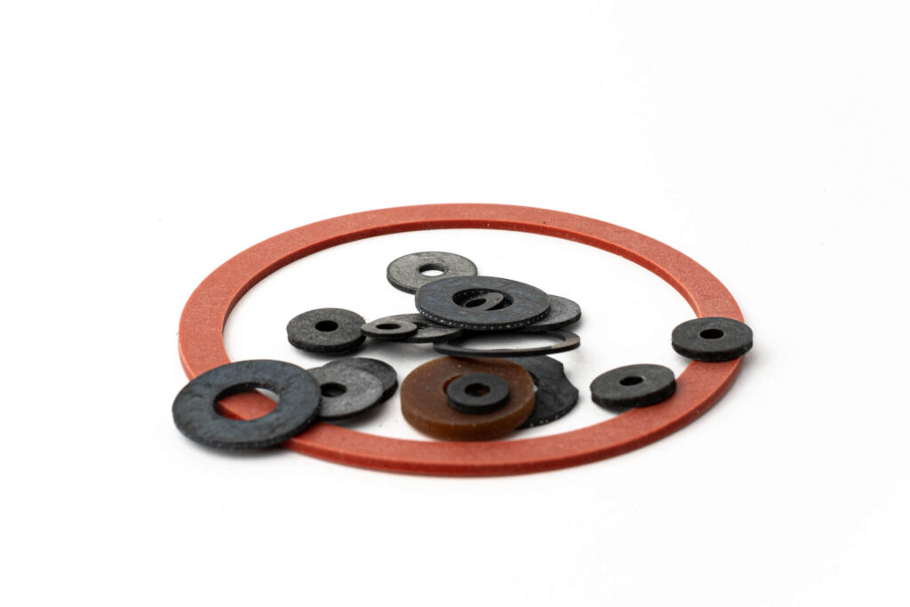
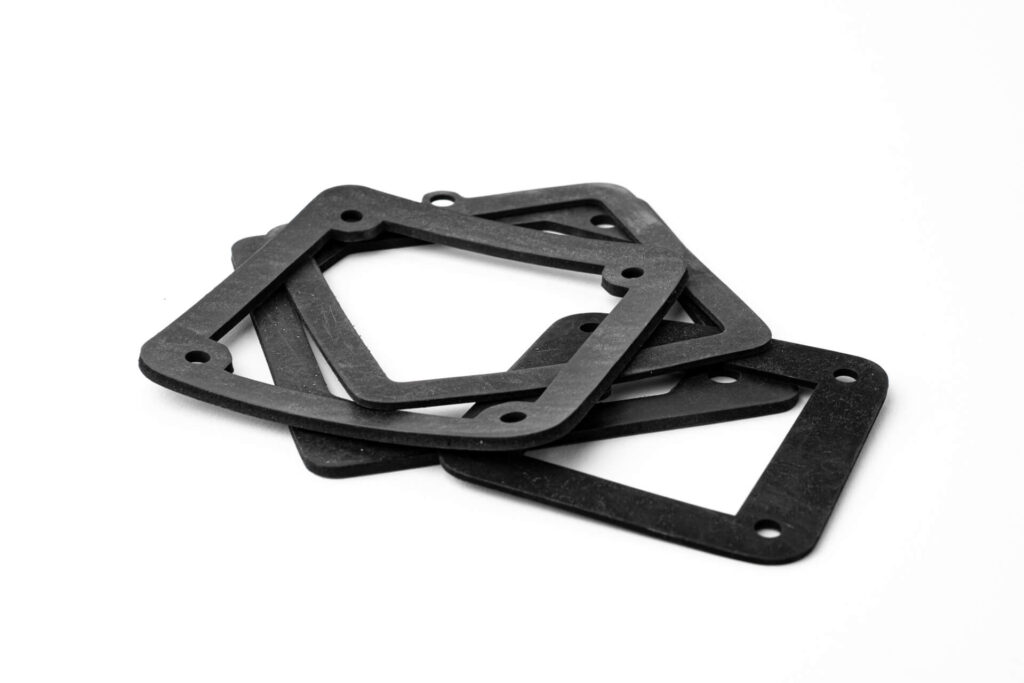
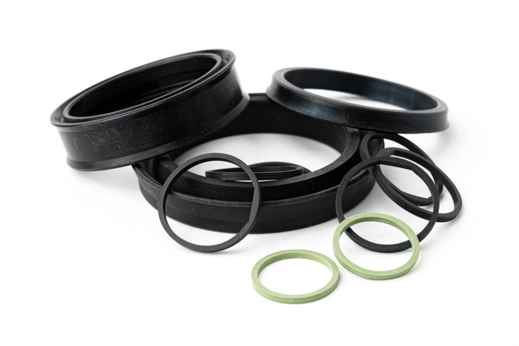
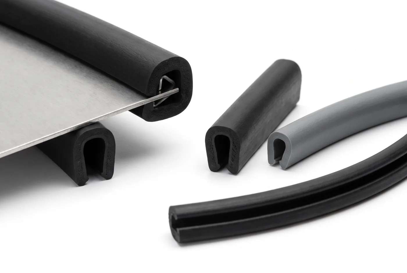
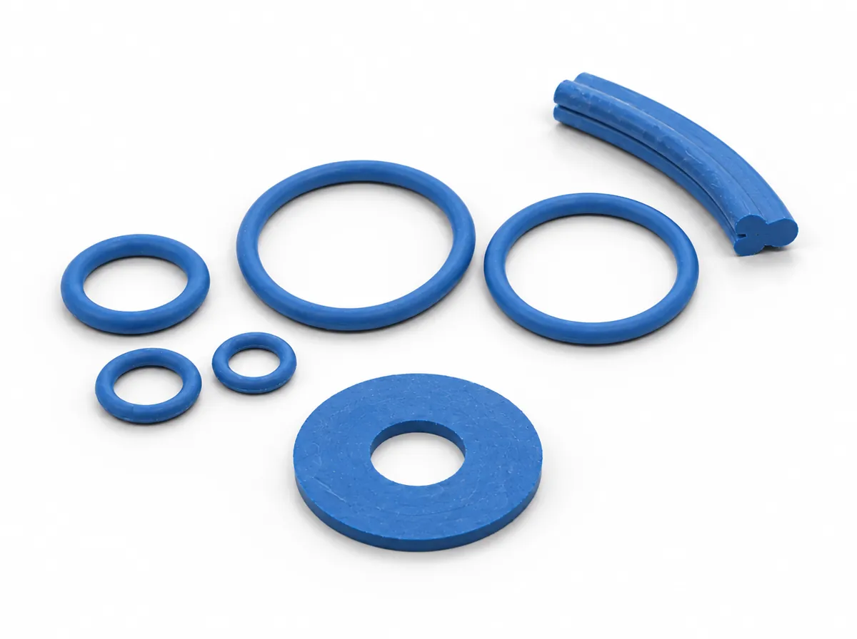
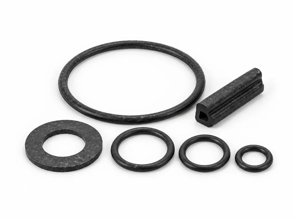
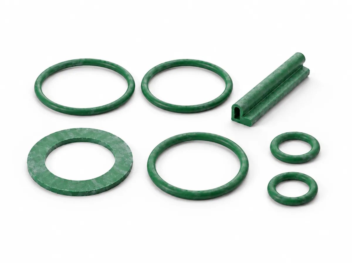
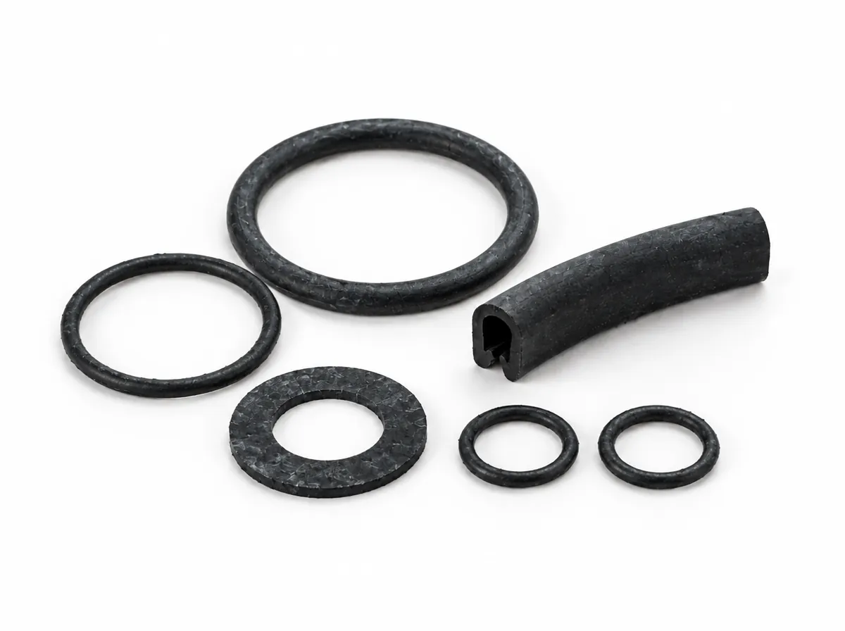
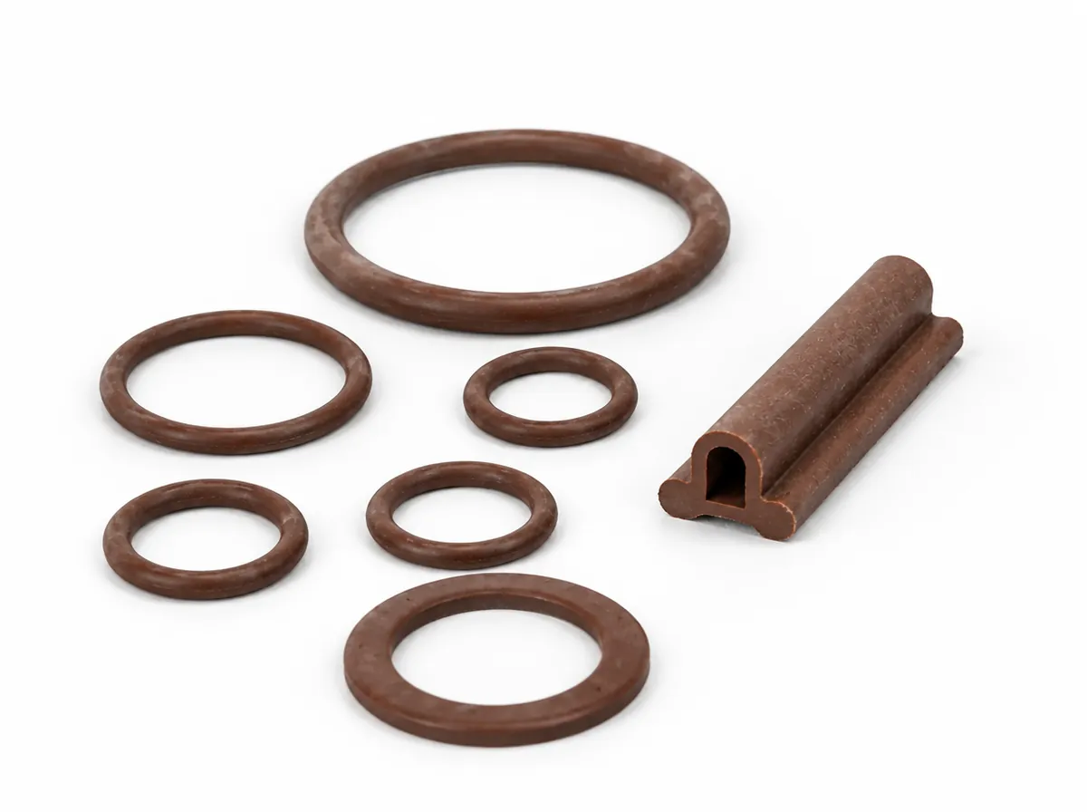
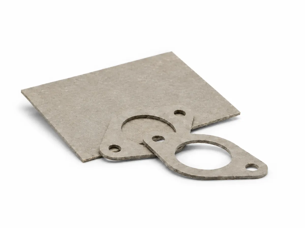
Tolerances describe the permissible deviations from the nominal values of a seal. Different DIN tolerances apply to each manufacturing process for rubber and plastic parts. Below you will find the relevant limit deviations for moulded parts, extruded parts, punched parts and sheet material, as well as for cut-in rings to DIN 46320.
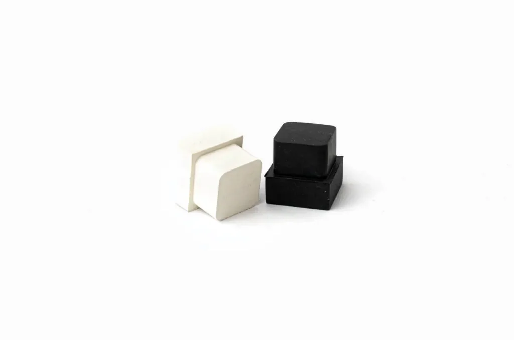
Moulded parts
DIN ISO 3302-1
Sheet material
DIN ISO 7715 T5
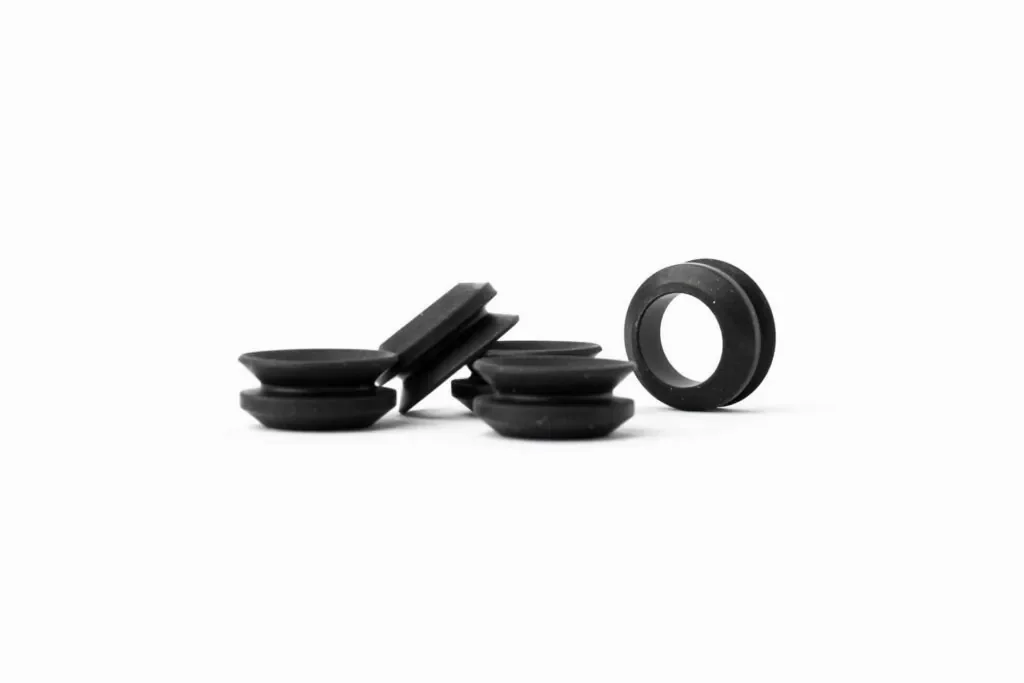
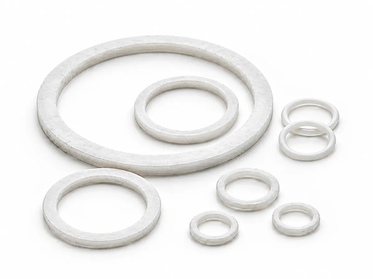
Sealing rings
DIN 46320 T1
Tolerance classes
M1-M4, P1-P3
Standards
Relevant standards for tolerances
Different tolerance standards apply depending on the manufacturing process. You will find the specific limit deviations in the tables below.
DIN ISO 3302-1
formerly DIN 7715
Limit deviations for finished parts, i.e. moulded parts and extruded parts.
DIN ISO 7715 Part 5
Tolerances for sheet material, the basis for punched parts. It distinguishes the tolerance classes P1, P2 and P3; DIN 7715 has no class "H1".
DIN 46320 Part 1
Tolerances for cut-out sealing rings.
Moulded parts
Limit deviations for moulded parts
Moulded parts
DIN ISO 3302-1, tolerance classes M1 to M4 (F and C)
| Nominal dimension | Tolerance class M1 | Tolerance class M2 | Tolerance class M3 | Tolerance class M4 | ||||
|---|---|---|---|---|---|---|---|---|
| over | up to | F | C | F | C | F | C | F and C |
| 0 | 4.0 | ± 0.08 | ± 0.10 | ± 0.10 | ± 0.15 | ± 0.25 | ± 0.40 | ± 0.50 |
| 4.0 | 6.3 | ± 0.10 | ± 0.12 | ± 0.15 | ± 0.20 | ± 0.25 | ± 0.40 | ± 0.50 |
| 6.3 | 10 | ± 0.10 | ± 0.15 | ± 0.20 | ± 0.20 | ± 0.30 | ± 0.50 | ± 0.70 |
| 10 | 16 | ± 0.15 | ± 0.20 | ± 0.20 | ± 0.25 | ± 0.40 | ± 0.60 | ± 0.80 |
| 16 | 25 | ± 0.20 | ± 0.20 | ± 0.25 | ± 0.35 | ± 0.50 | ± 0.80 | ± 1.00 |
| 25 | 40 | ± 0.20 | ± 0.25 | ± 0.35 | ± 0.40 | ± 0.60 | ± 1.00 | ± 1.30 |
| 40 | 63 | ± 0.25 | ± 0.35 | ± 0.40 | ± 0.50 | ± 0.80 | ± 1.30 | ± 1.60 |
| 63 | 100 | ± 0.35 | ± 0.40 | ± 0.50 | ± 0.70 | ± 1.00 | ± 1.60 | ± 2.00 |
| 100 | 160 | ± 0.40 | ± 0.50 | ± 0.70 | ± 0.80 | ± 1.30 | ± 2.00 | ± 2.50 |
| 160 | - | ± 0.3 % | ± 0.4 % | ± 0.5 % | ± 0.7 % | ± 0.8 % | ± 1.3 % | ± 1.5 % |
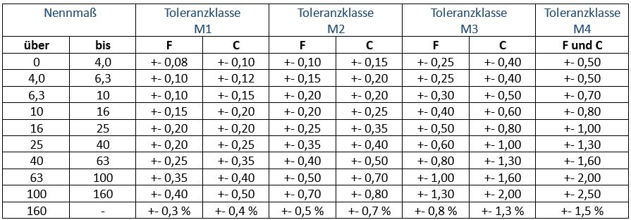
Table as image
Download (JPG, 73 KB)Extruded parts
Limit deviations for extruded parts
Internal dimensions of extruded parts produced on a mandrel
DIN ISO 3302-1, tolerance classes EN1 to EN3
| Nominal dimension | Tolerance class EN1 | Tolerance class EN2 | Tolerance class EN3 | |
|---|---|---|---|---|
| over | up to | |||
| 0 | 4.0 | ± 0.20 | ± 0.20 | ± 0.35 |
| 4.0 | 6.3 | ± 0.20 | ± 0.25 | ± 0.40 |
| 6.3 | 10 | ± 0.25 | ± 0.35 | ± 0.50 |
| 10 | 16 | ± 0.35 | ± 0.40 | ± 0.70 |
| 16 | 25 | ± 0.40 | ± 0.50 | ± 0.80 |
| 25 | 40 | ± 0.50 | ± 0.70 | ± 1.00 |
| 40 | 63 | ± 0.70 | ± 0.80 | ± 1.30 |
| 63 | 100 | ± 0.80 | ± 1.00 | ± 1.60 |
| 100 | 160 | ± 1.00 | ± 1.30 | ± 2.00 |
| 160 | - | ± 0.6 % | ± 0.8 % | ± 1.2 % |
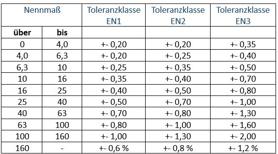
Table as image
Download (JPG, 40 KB)External dimensions of ground extruded parts
DIN ISO 3302-1, tolerance classes EG1 and EG2
| Nominal dimension | Tolerance class EG1 | Tolerance class EG2 | |
|---|---|---|---|
| over | up to | ||
| 0 | 10 | ± 0.15 | ± 0.25 |
| 10 | 16 | ± 0.20 | ± 0.35 |
| 16 | 25 | ± 0.20 | ± 0.40 |
| 25 | 40 | ± 0.25 | ± 0.50 |
| 40 | 63 | ± 0.35 | ± 0.70 |
| 63 | 100 | ± 0.40 | ± 0.80 |
| 100 | 160 | ± 0.50 | ± 1.00 |
| 160 | - | ± 0.3 % | ± 0.5 % |
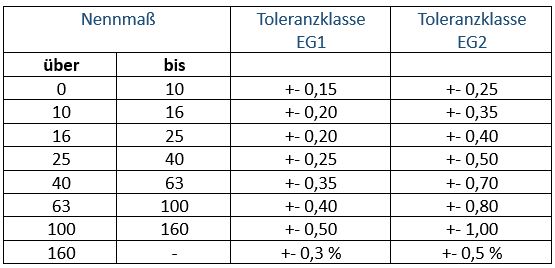
Table as image
Download (JPG, 28 KB)Cut lengths of extruded parts
DIN ISO 3302-1, tolerance classes L1 to L3
| Nominal length | Tolerance class L1 | Tolerance class L2 | Tolerance class L3 | |
|---|---|---|---|---|
| over | up to | |||
| 0 | 40 | ± 0.7 | ± 1.0 | ± 1.6 |
| 40 | 63 | ± 0.8 | ± 1.3 | ± 2.0 |
| 63 | 100 | ± 1.0 | ± 1.6 | ± 2.5 |
| 100 | 160 | ± 1.3 | ± 2.0 | ± 3.2 |
| 160 | 250 | ± 1.6 | ± 2.5 | ± 4.0 |
| 250 | 400 | ± 2.0 | ± 3.2 | ± 5.0 |
| 400 | 630 | ± 2.5 | ± 4.0 | ± 6.3 |
| 630 | 1000 | ± 3.2 | ± 5.0 | ± 10.0 |
| 1000 | 1600 | ± 4.0 | ± 6.3 | ± 12.5 |
| 1600 | 2500 | ± 5.0 | ± 10.0 | ± 16.0 |
| 2500 | 4000 | ± 6.3 | ± 12.5 | ± 20.0 |
| 4000 | - | ± 0.16 % | ± 0.32 % | ± 0.50 % |
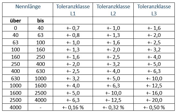
Table as image
Download (JPG, 46 KB)Thickness of cut sections
DIN ISO 3302-1, tolerance classes EC1 to EC3
| Nominal thickness | Tolerance class EC1 | Tolerance class EC2 | Tolerance class EC3 | |
|---|---|---|---|---|
| over | up to | |||
| 0.63 | 1.00 | ± 0.10 | ± 0.15 | ± 0.20 |
| 1.00 | 1.60 | ± 0.10 | ± 0.20 | ± 0.25 |
| 1.60 | 2.50 | ± 0.15 | ± 0.20 | ± 0.35 |
| 2.50 | 4.00 | ± 0.20 | ± 0.25 | ± 0.40 |
| 4.00 | 6.30 | ± 0.20 | ± 0.35 | ± 0.50 |
| 6.30 | 10.00 | ± 0.25 | ± 0.40 | ± 0.70 |
| 10.00 | 16.00 | ± 0.35 | ± 0.50 | ± 0.80 |
| 16.00 | 25.00 | ± 0.40 | ± 0.70 | ± 1.00 |
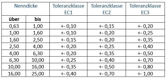
Table as image
Download (JPG, 37 KB)Cross-sections of unsupported extruded parts
DIN ISO 3302-1, tolerance classes E1 to E3
| Nominal thickness | Tolerance class E1 | Tolerance class E2 | Tolerance class E3 | |
|---|---|---|---|---|
| over | up to | |||
| 0 | 1.5 | ± 0.15 | ± 0.25 | ± 0.40 |
| 1.5 | 2.5 | ± 0.20 | ± 0.35 | ± 0.50 |
| 2.5 | 4.0 | ± 0.25 | ± 0.40 | ± 0.70 |
| 4.0 | 6.3 | ± 0.35 | ± 0.50 | ± 0.80 |
| 6.3 | 10.0 | ± 0.40 | ± 0.70 | ± 1.00 |
| 10.0 | 16.0 | ± 0.50 | ± 0.80 | ± 1.30 |
| 16.0 | 25.0 | ± 0.70 | ± 1.00 | ± 1.60 |
| 25.0 | 40.0 | ± 0.80 | ± 1.30 | ± 2.00 |
| 40.0 | 63.0 | ± 1.00 | ± 1.60 | ± 2.50 |
| 63.0 | 100 | ± 1.30 | ± 2.00 | ± 3.20 |
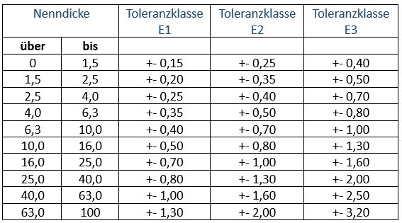
Table as image
Download (JPG, 42 KB)Punched parts
Limit deviations for punched parts and sheet material
Thickness of calendered sheets
Basis for punched parts, tolerance classes ST1 to ST3
| Nominal thickness | Tolerance class ST1 | Tolerance class ST2 | Tolerance class ST3 | |
|---|---|---|---|---|
| over | up to | |||
| 0 | 1.00 | ± 0.15 | ± 0.20 | ± 0.25 |
| 1.00 | 1.60 | ± 0.15 | ± 0.25 | ± 0.35 |
| 1.60 | 2.50 | ± 0.20 | ± 0.35 | ± 0.40 |
| 2.50 | 4.00 | ± 0.25 | ± 0.40 | ± 0.50 |
| 4.00 | 6.30 | ± 0.35 | ± 0.50 | ± 0.70 |
| 6.30 | 10.00 | ± 0.40 | ± 0.70 | ± 0.80 |
| 10.00 | 16.00 | ± 0.50 | ± 0.80 | ± 1.00 |
| 16.00 | - | ± 3.5 % | ± 5 % | ± 7 % |
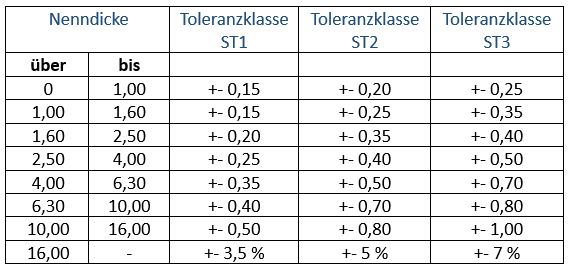
Table as image
Download (JPG, 36 KB)Sheet material for punched parts
DIN ISO 7715 Part 5, tolerance classes P1 to P3
| Nominal dimension | Tolerance class P1 | Tolerance class P2 | Tolerance class P3 | |
|---|---|---|---|---|
| over | up to | |||
| 0 | 1.60 | ± 0.20 | ± 0.20 | ± 0.40 |
| 1.60 | 4.00 | ± 0.20 | ± 0.30 | ± 0.40 |
| 4.00 | 6.30 | ± 0.20 | ± 0.40 | ± 0.50 |
| 6.30 | 10.00 | ± 0.30 | ± 0.50 | ± 0.60 |
| 10.00 | 25.00 | ± 0.30 | ± 0.60 | ± 0.80 |
| 25.00 | 40.00 | ± 0.40 | ± 0.80 | ± 1.00 |
| 40.00 | 63.00 | ± 0.50 | ± 1.00 | ± 1.50 |
| 63.00 | 100.00 | ± 0.60 | ± 1.20 | ± 2.00 |
| 100.00 | 160.00 | ± 0.80 | ± 1.40 | ± 2.50 |
| 160.00 | 250.00 | ± 1.00 | ± 1.60 | ± 3.00 |
| 250.00 | 400.00 | ± 1.60 | ± 2.50 | ± 5.00 |
| 400.00 | - | ± 0.50 % | ± 0.80 % | ± 1.50 % |
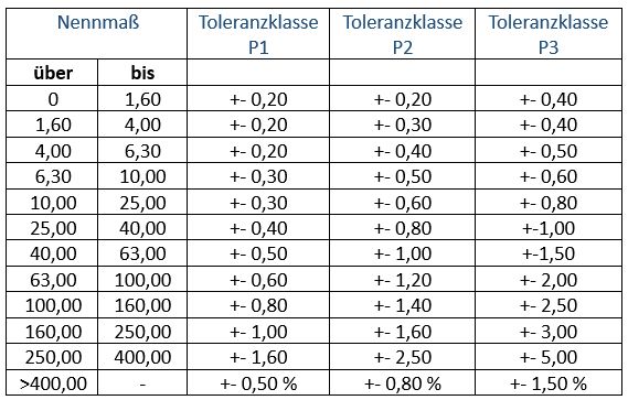
Table as image
Download (JPG, 53 KB)Cut-in rings
Tolerances for cut-in sealing rings to DIN 46320 Part 1
Permissible deviations and assignment to cable and wire diameters and the matching PG cable gland. Tolerance on diameters D3, D4 and D5: ±0.5 mm each. All dimensions in mm.
Cut-in rings (onion seals) for cable glands
DIN 46320 Part 1, PG 9 to PG 48
| Sealing ring dimensions | Usable for cable and wire diameters | Cable gland | ||||||||
|---|---|---|---|---|---|---|---|---|---|---|
| D1 | D2 | D3 | D4 | D5 | S | at D2 | at D3 | at D4 | at D5 | |
| 13.3 ±0.5 | 5 ±0.25 | 7.5 | 10 | - | 5.5 ±0.4 | 4 to 6 | 6.5 to 8.5 | 9 to 11 | - | PG 9 |
| 16.5 ±0.7 | 7.5 ±0.35 | 10 | 12.5 | - | 6 ±0.5 | 6.5 to 8.5 | 9 to 11 | 11.5 to 13.5 | - | PG 11 |
| 18.3 ±0.7 | 7.5 ±0.35 | 10 | 12.5 | - | 6 ±0.5 | 6.5 to 8.5 | 9 to 11 | 11.5 to 13.5 | - | PG 13.5 |
| 20.4 ±0.7 | 7.5 ±0.35 | 10 | 12.5 | 15 | 7 ±0.5 | 6.5 to 8.5 | 9 to 11 | 11.5 to 13.5 | 14 to 16 | PG 16 |
| 25.9 ±0.8 | 10 ±0.35 | 13 | 16 | 19 | 8 ±0.5 | 9 to 11 | 12 to 14 | 15 to 17 | 18 to 21 | PG 21 |
| 34.7 ±0.8 | 18 ±0.5 | 21 | 24 | 27 | 9.5 ±0.6 | 17 to 19 | 20 to 22 | 23 to 25 | 26 to 28 | PG 29 |
| 44.7 ±0.8 | 24 ±0.5 | 27 | 30 | 33 | 12 ±0.6 | 23 to 25 | 26 to 28 | 29 to 31 | 32 to 34 | PG 36 |
| 51.7 ±0.8 | 30 ±0.7 | 33 | 36 | 39 | 14 ±0.6 | 29 to 31 | 32 to 34 | 35 to 37 | 38 to 40 | PG 42 |
| 56.9 ±0.9 | 36 ±0.7 | 39 | 42 | 45 | 14 ±0.6 | 35 to 37 | 38 to 40 | 41 to 43 | 44 to 46 | PG 48 |
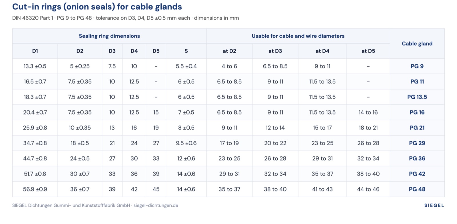
Table as image
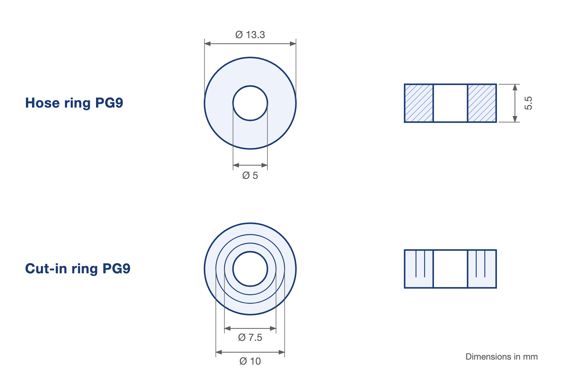
Download (JPG, 178 KB)Example: cut-in ring for a PG 9 cable gland
- D1 = outer diameter of the sealing ring (PG 9 = 13.3 mm)
- D2 = inner diameter of the sealing ring (PG 9 = 5 mm)
- S = cut thickness / height of the sealing ring (PG 9 = 5.5 mm)
- D3, D4, D5 = diameters of the cut-ins, removable with a knife or by hand (PG 9 = 7.5 / 10 mm)
More on design, materials and versions: cut-in rings from SIEGEL
Working together
Questions about tolerances for your component?
Tell us the manufacturing process, material and dimensions, and we will advise you on the right tolerance classes and the right design.